Autodesk Fusion 360 Guide #
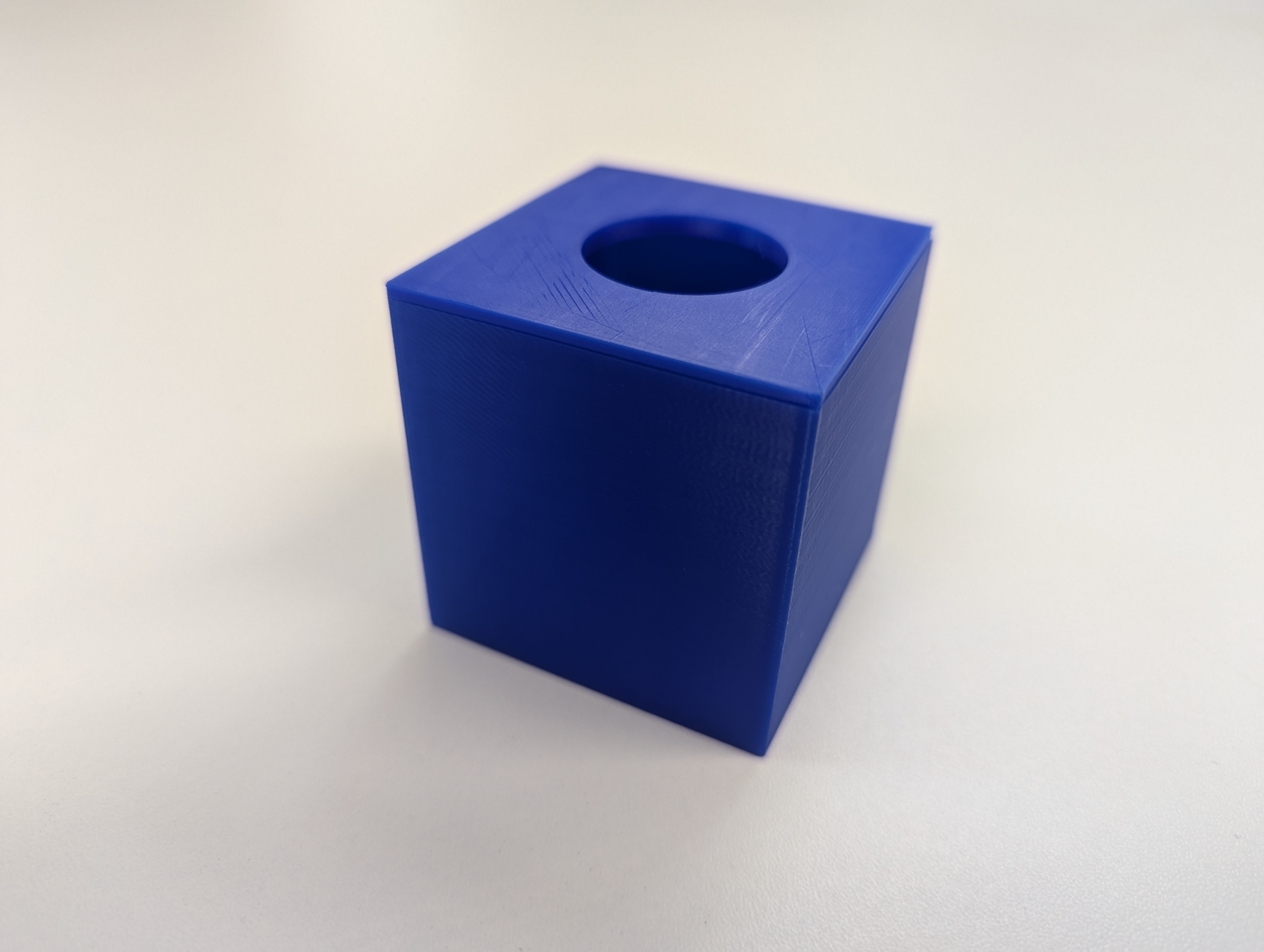
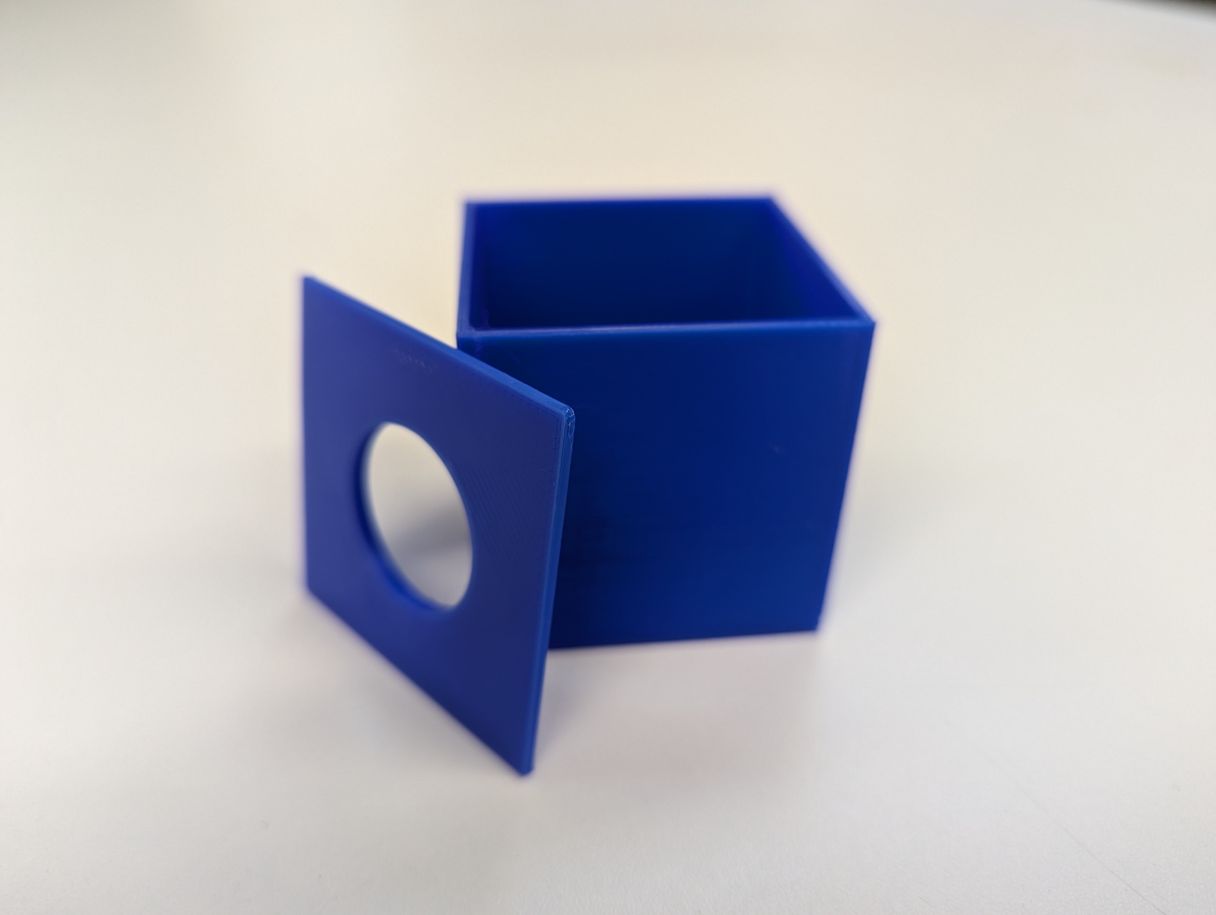
This guide will provide an introduction to Computer Aided Design (CAD) with Autodesk Fusion 360. In this tutorial, we shall make a small box, with a lid and cover:
Autodesk Fusion 360 Installation Guide #
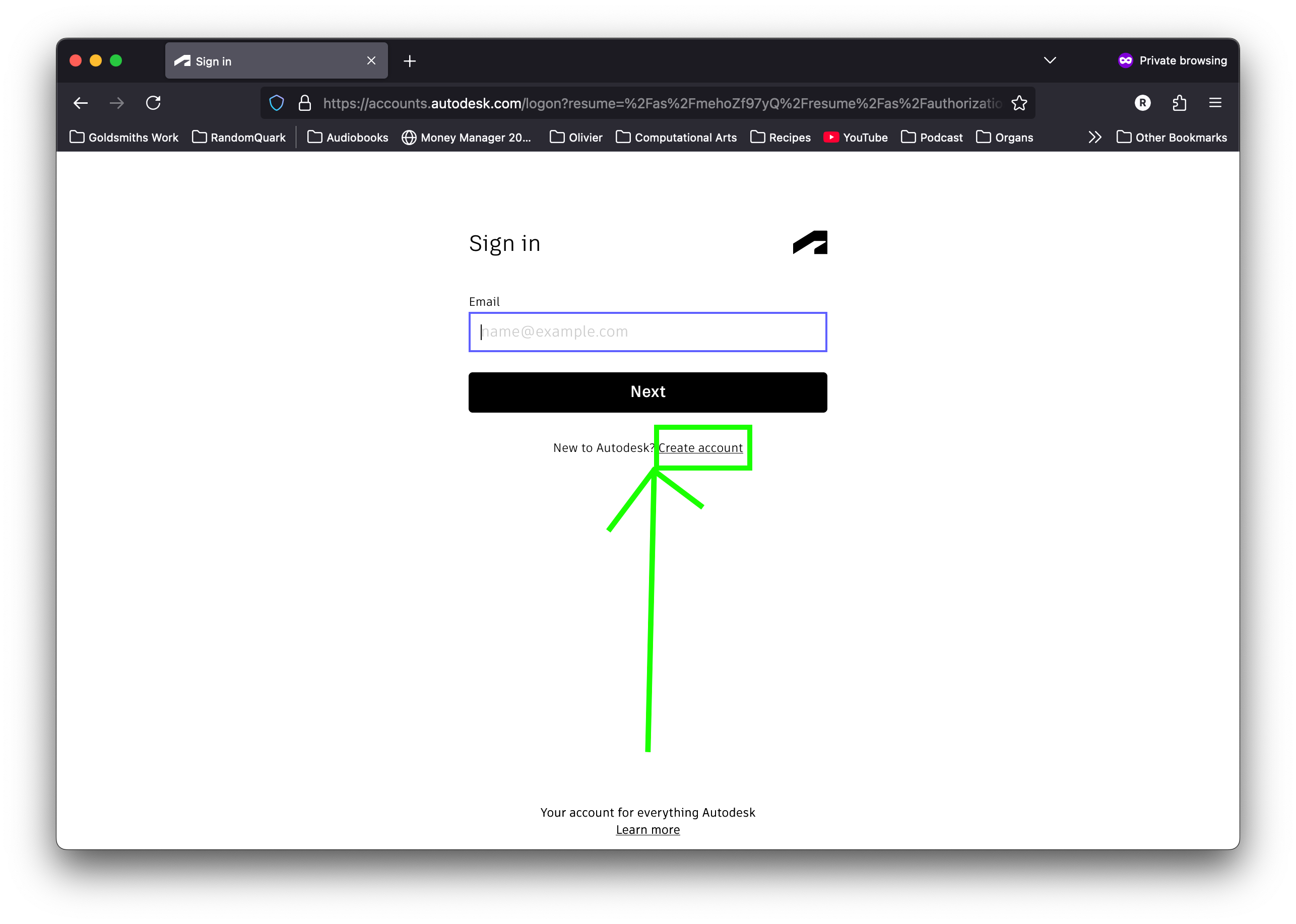
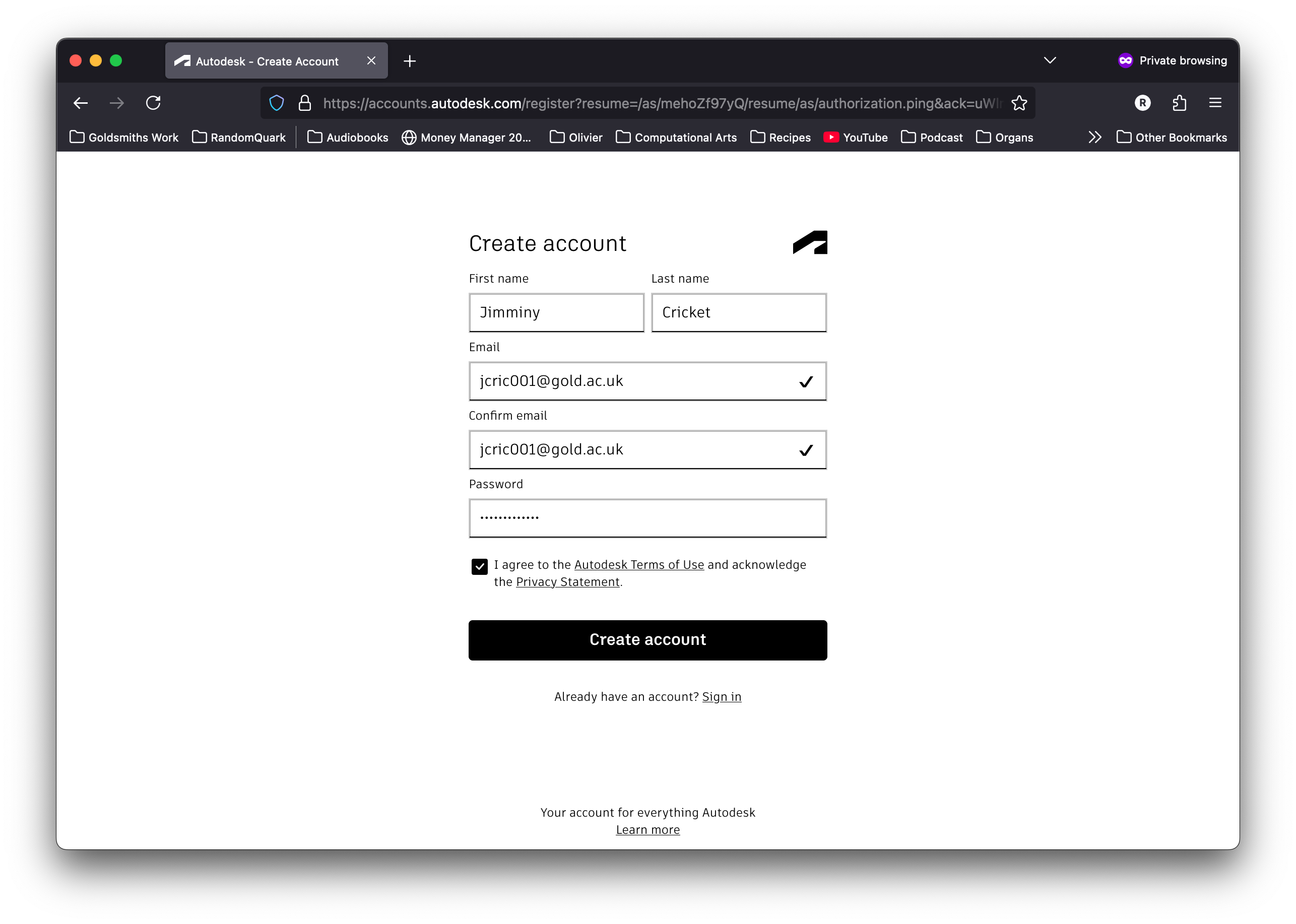
Step 1: Create an Autodesk Account
Follow the link and create an account on Autodesk’s website using your Goldsmiths email: https://www.autodesk.com/uk

Step 2: Download Fusion 360
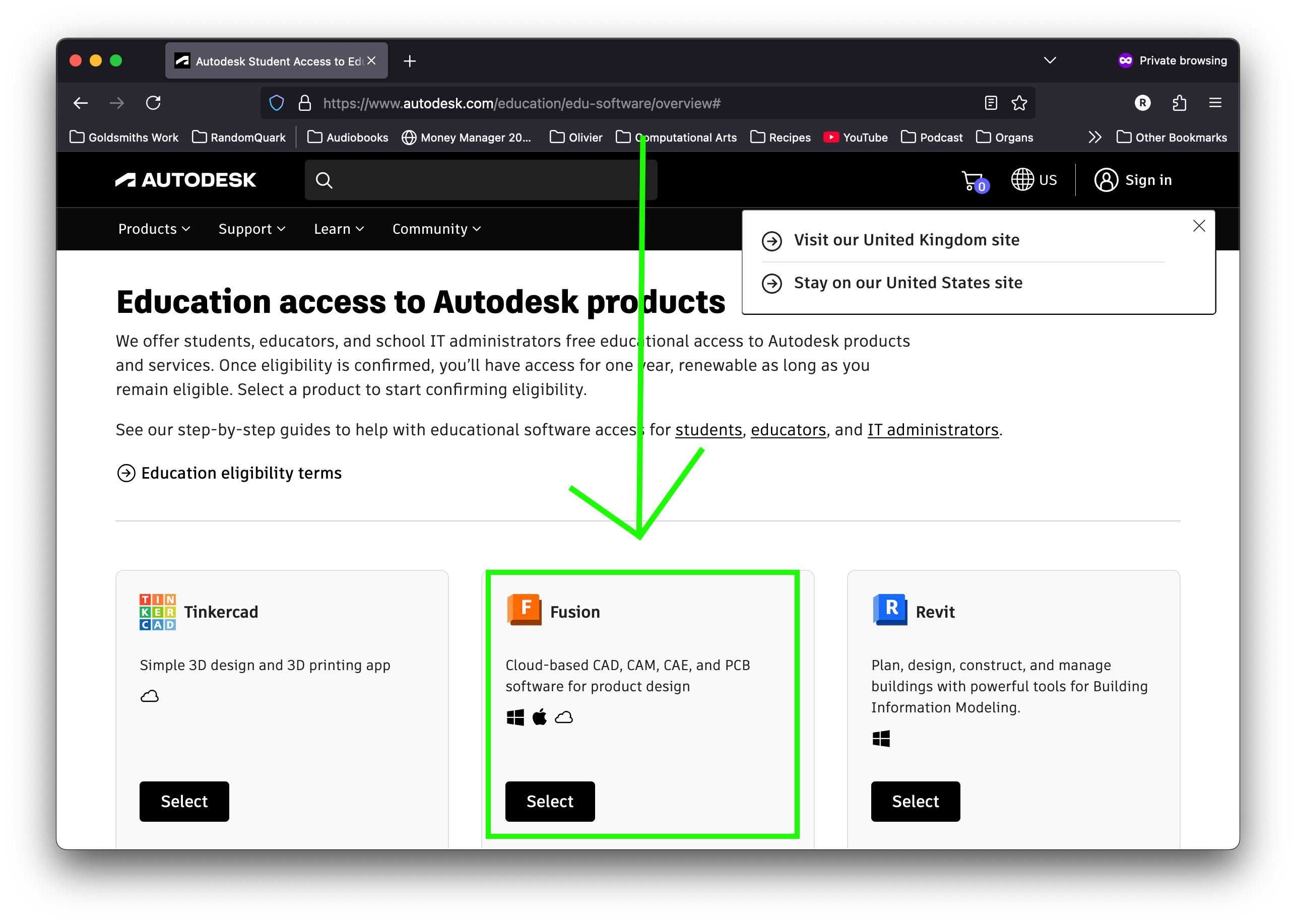
Follow this link to the education section of the Autodesk site: https://www.autodesk.com/education/edu-software/overview
- Select Fusion
- Select Student
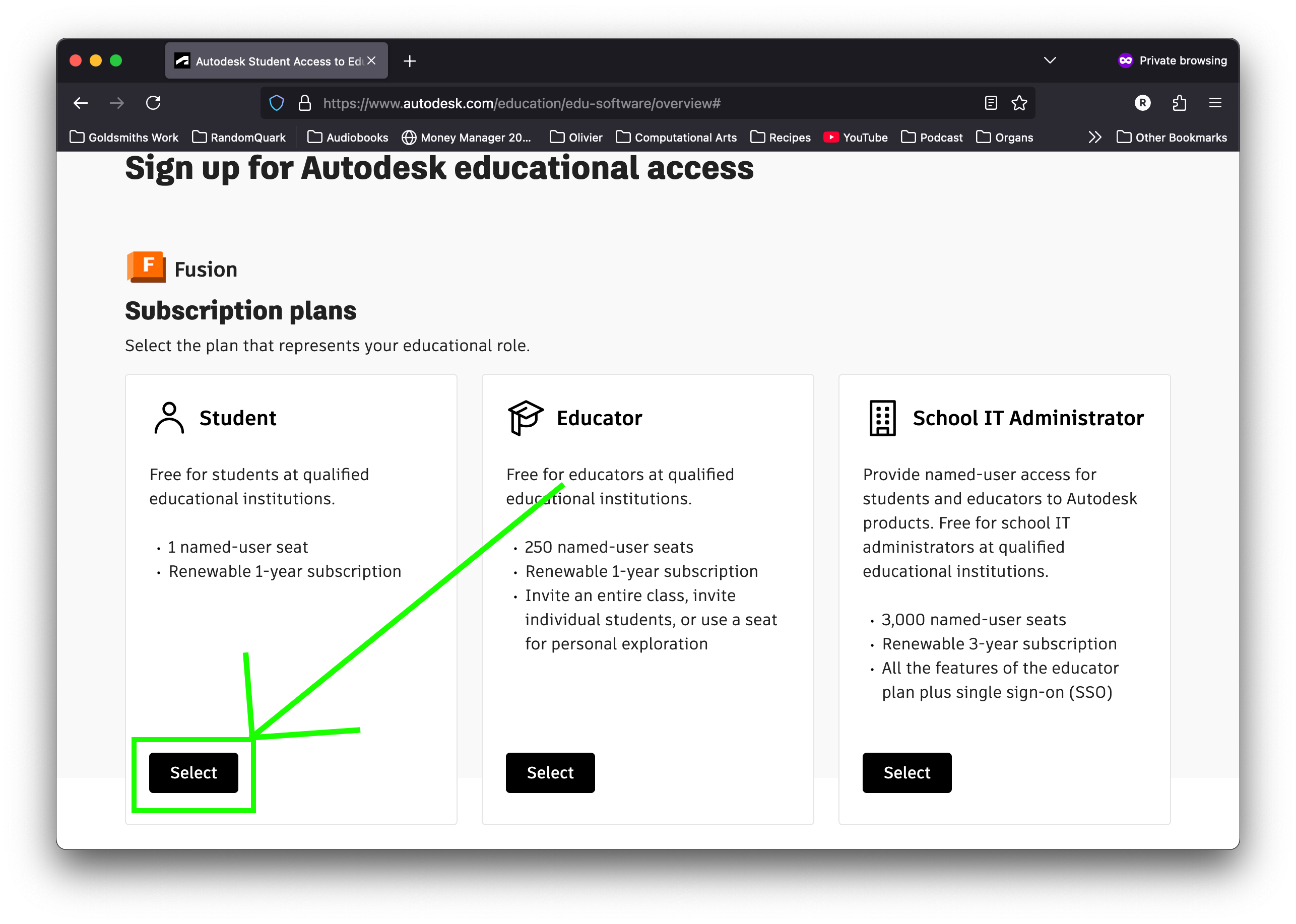
- Hit Submit
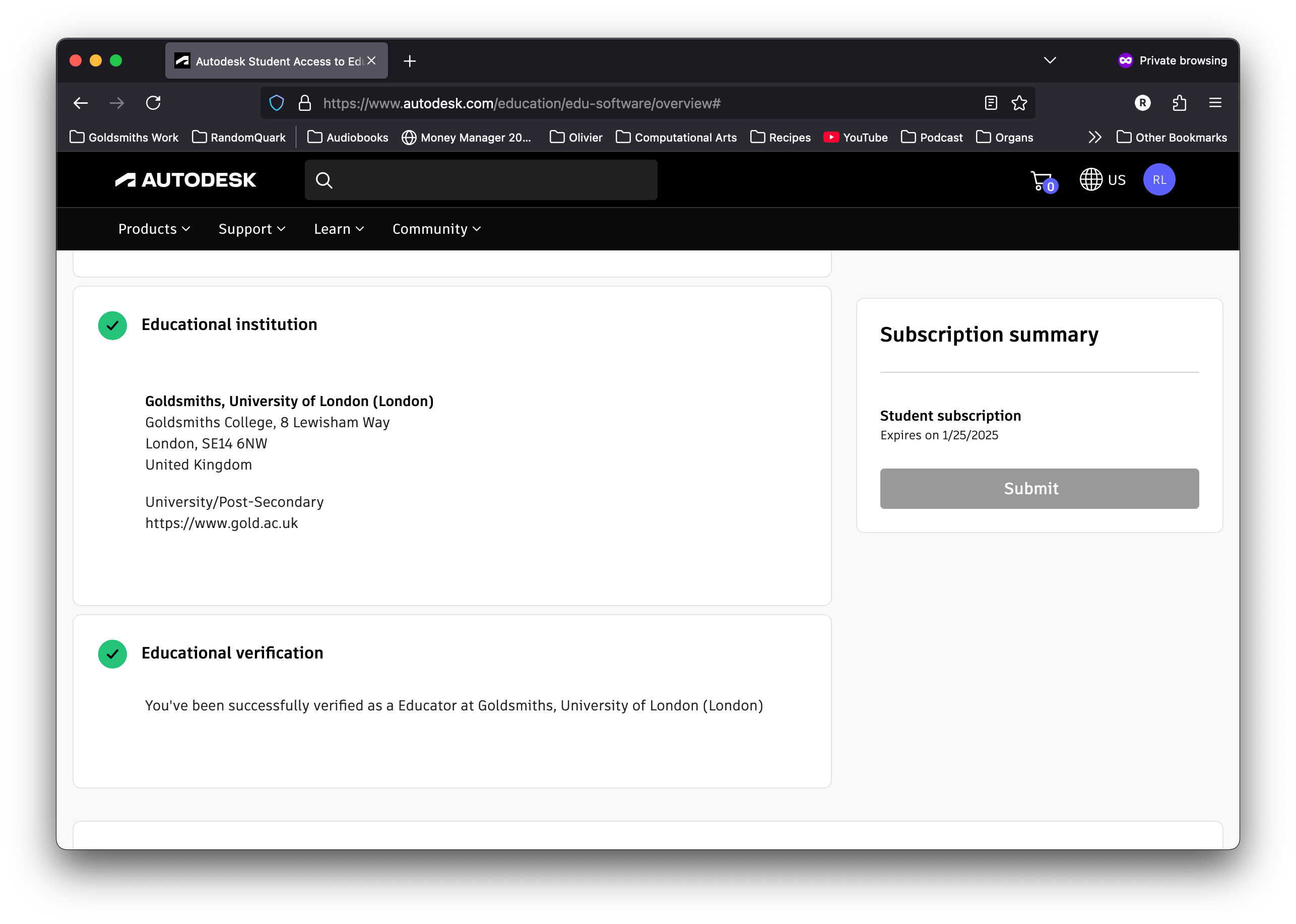
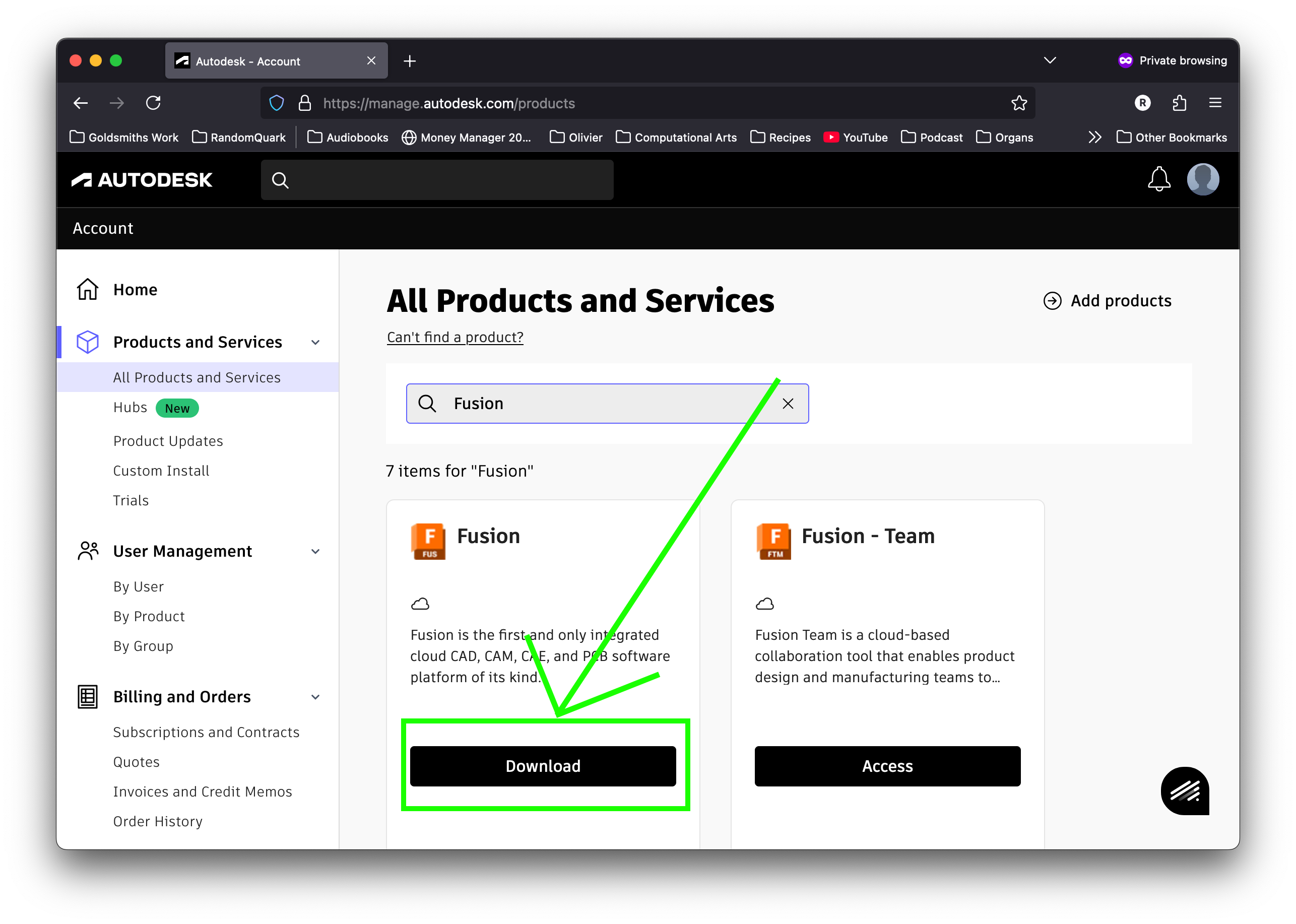
- Click “Access Products” Or go here
- Download Fusion
The Interface #
Creating our First Sketch #
- Click on the Create Sketch button, located in the top left corner of the Design workspace.
- Select the ground plane. This should open us into an orthographic view of our plane, and show the sketching tools in the toolbar.
 3. Click on the 2-point rectangle button, located in the top left of the window, in the Create tab.
4. We should be given a context menu on our right hand side. Let’s select Center Rectangle from this menu.
5. Place our centre point at the origin of our axes.
6. Place one of our corners. (I’ve placed it at (-50, 50), which will create a rectangle of 100 x 100, but we will be controlling these dimensions parametrically next, so you can place it anywhere)
3. Click on the 2-point rectangle button, located in the top left of the window, in the Create tab.
4. We should be given a context menu on our right hand side. Let’s select Center Rectangle from this menu.
5. Place our centre point at the origin of our axes.
6. Place one of our corners. (I’ve placed it at (-50, 50), which will create a rectangle of 100 x 100, but we will be controlling these dimensions parametrically next, so you can place it anywhere)
 7. Go to the Modify dropdown menu, and select Change Parameters.
8. Click the + symbol to add a new parameter.
9. Let’s create parameters for:
7. Go to the Modify dropdown menu, and select Change Parameters.
8. Click the + symbol to add a new parameter.
9. Let’s create parameters for:
- Box_Width: 100mm
- Box_Height: 100mm
- Box_Depth: 100mm
- Box_Wall_Thickness: 3mm
 10. Under the Create tab, let’s select Sketch Dimension, and select one of the edges denoting the width of our box, dragging our dimension dialog somewhere sensibly visible.
11. In the dialog box, begin typing “Box_Width”, and select it from the dropdown menu. This will allow us to control the size of our box from the parameters menu in future.
12. Repeat this step for one of the perpendicular edges of the rectangle, inputting “Box_Depth”. Press OK to close the parameters menu.
10. Under the Create tab, let’s select Sketch Dimension, and select one of the edges denoting the width of our box, dragging our dimension dialog somewhere sensibly visible.
11. In the dialog box, begin typing “Box_Width”, and select it from the dropdown menu. This will allow us to control the size of our box from the parameters menu in future.
12. Repeat this step for one of the perpendicular edges of the rectangle, inputting “Box_Depth”. Press OK to close the parameters menu.
 13. Select the Offset tool from the Modify tab.
14. Select the outline of our rectangle, and input the value of our Box_Wall_Thickness, making sure the offset is inside our original rectangle. Hit OK, and exit the Sketch workspace by pressing the Finish Sketch button in the top right of the workspace.
13. Select the Offset tool from the Modify tab.
14. Select the outline of our rectangle, and input the value of our Box_Wall_Thickness, making sure the offset is inside our original rectangle. Hit OK, and exit the Sketch workspace by pressing the Finish Sketch button in the top right of the workspace.
 15. Back in the Design Workspace, let’s select the Extrude tool, and then pick the face created by our offset.
16. In the dialog box, enter Box_Height, and click OK to accept.
15. Back in the Design Workspace, let’s select the Extrude tool, and then pick the face created by our offset.
16. In the dialog box, enter Box_Height, and click OK to accept.
 17. Our original sketch will have been hidden. We can find it under the Sketches folder dropdown, clicking the eye symbol next to our Sketch1 to reveal it.
18. Select the inner face of the sketch, and then Extrude inputting our Box_Wall_Thickness parameter into the dialog box. Be sure that the Operation dropdown is set to Join, and select OK.
17. Our original sketch will have been hidden. We can find it under the Sketches folder dropdown, clicking the eye symbol next to our Sketch1 to reveal it.
18. Select the inner face of the sketch, and then Extrude inputting our Box_Wall_Thickness parameter into the dialog box. Be sure that the Operation dropdown is set to Join, and select OK.
 19.
19.
 20.
20.
Tolerances #
Exporting for 3D Printing #
 To export (say for 3D printing), in the left side browser menu make visible all the bodies you wish to export.
Right click on the component name at the top, and select “Save As Mesh”.
Use .obj or .stl format, and save in a place of your choosing.
To export (say for 3D printing), in the left side browser menu make visible all the bodies you wish to export.
Right click on the component name at the top, and select “Save As Mesh”.
Use .obj or .stl format, and save in a place of your choosing.